K6 Re-Install and New Indirect HWH

I got a great deal on a Triangle Tube indirect hot water heater and this coming weekend I'm going to install it and re-install the K6. I came up with a design idea and would like to bounce it off the people here for some feedback. I haven't decided if I want to use the existing Taco 007 circulator or go to a larger size like the 0011 or 0014. I also picked up a Taco ZVC405 zone control panel to make the wiring easy.


I also have a B&G NRF-22 new in the box that has more GPM and Head than the TACO 007. I think I'll go with the B&G instead of spending a couple hundred bucks on a new oversized pump.
-
Sting

- Member
- Posts: 2983
- Joined: Mon. Feb. 25, 2008 4:24 pm
- Location: Lower Fox Valley = Wisconsin
- Other Heating: OBSO Lennox Pulse "Air Scorcher" burning NG
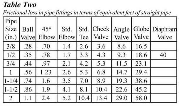
That's a very nice drawing but it lacks length and fitting information to do a lucid calcualtion
Just a reaction: The existing pump will work fine!
But if you want to get techie
Just a reaction: The existing pump will work fine!
But if you want to get techie
yeah it is lacking a lot of useful information as far as correctly sizing the pump. But then again there isnt any information on the Keystoker (pressure drop) to help correctly size a pump. The 007 was fine with just the oil boiler, but with the two boilers hooked up in series it didn't work well at all. I also think that the 007 would work just fine, but the B&G has a little oomph in case it might be needed.
The drawing is mostly just to show the layout of the equipment.
Thanks for the help!
The drawing is mostly just to show the layout of the equipment.
Thanks for the help!
-
Sting
- Member
- Posts: 2983
- Joined: Mon. Feb. 25, 2008 4:24 pm
- Location: Lower Fox Valley = Wisconsin
- Other Heating: OBSO Lennox Pulse "Air Scorcher" burning NG
Lets remember that too much or too large a pump is not a good thing either. Often its worse than better.
There are lots of series installations working just fine on the existing pump. Could some other drama be afoot causing a flow issue other than a second boiler to circulate in the system? IF YES- turning up the pressure with a larger pump is going to create other havoc and as trouble piles on trouble -- well the system suffers and you will burn more fuel to gain the requested result!
I am sure other wet guys that think I am nuts will be alone soon to help figure the correct path for the smoking rabbit.
Sting wrote: I am sure other wet guys that think I am nuts will be alone soon to help figure the correct path for the smoking rabbit.
In another thread when we discussed some of the issues I was having we (I think it was you actually) determined that the use of 1" pipe between the boilers was not a good idea. All of the piping in the original oil setup used 1" and the guy that helped me install the coal boiler continued the use of 1" pipe between the boilers and back up into the system. I know the 1" pipe off the oil will be ok, and I'll use 1 1/4" supply from the coal into a 1" header above. The instructions for the K6 note that 1 1/4" must be used on the supply side. Why we didn't do this to begin with is beyond me.
So if I go with the design I posted here and use the 007, it will be fine? I'd hate to reinstall it only to find out it's not sufficient.
well, today's the day. Wish me luck.


All done! Only 1 small leak in a mess of piping, but its piped!
I havent installed the taco zone controller yet as I need a break from being in the mech room for two whole days. I have a question regarding the wiring of a honeywell V8043E motorized zone valve that is piped into the hot water heater. I want to hook it up so I can make hot water right now and that's it. I cannot find a decent straight-forward wiring diagram anywhere online. It's an existing unit and I lost track of the existing wires because it looked like a bowl of noodles.
There are two red wires and two yellow wires. Can someone please explain how to hook these up to with my boiler and my HWH.
Thanks.
ps - Hey Sting, I found a post by you on another forum regarding wiring of a unit sorta similar to the V8043, but I'm still very confused.
-
Sting
- Member
- Posts: 2983
- Joined: Mon. Feb. 25, 2008 4:24 pm
- Location: Lower Fox Valley = Wisconsin
- Other Heating: OBSO Lennox Pulse "Air Scorcher" burning NG
You think you confused -- you should be on this side of the public internet 
http://www.forwardthinking.honeywell.com/related_ ... _10932.pdf
The two yellows are from (and to) a powered 24 volt control -- Can you say Thermostat - or Aquastat
and when the device receives a 24 volt signal and ground on these yellow wires the 24 volt motor rotates the valve open!
Now when the motor opens the normally closed valve, the two reds ( normally open) are connected (closed) and you have a circuit that will hold a 15 amp load -- like a fan or a pump or ??? -- as long as the signal is holding the valve open -- when the signal is lost - as when a zone thermostat stops calling for heat - the valve looses its power - the valve closes (stopping liquid flow) - and the connection of the red wires opens......
Or another way the yellows are the switch to open the normally closed valve --- and the reds are normally open but close when the valve is open.....
Now -- make some hot water --- but make sure you don't send DHW out to the taps above code set temp of 120 degrees!
On the 24v transformer I have the following.
(1) wire connected to the "R" terminal. This wire goes to one terminal on the thermostat for the HWH.
(1) wire connected to the "C" terminal. This wire goes to one of the yellow wires on the zone valve.
The other yellow wire from the zone valve goes to the other terminal on the thermostat.
The two red wires on the zone valve go to the TT connections on the aquastat on the boiler.
Its wired just like this http://customer.honeywell.com/techlit/images/gif/M5953.gif
I turn the power on the boiler, which also powers the 24v transformer and the boiler starts running and the zone valve opens. When the boiler reaches temp it turns off. I had the temp set at normal on the HWH, but I turned it to LOW to see if the valve would close - and it did not. Im assuming if I turn the temp to LOW the zone valve would close.
Am I wired correctly and just not being patient with the zone valve?
Thanks for all your help
-
Sting
- Member
- Posts: 2983
- Joined: Mon. Feb. 25, 2008 4:24 pm
- Location: Lower Fox Valley = Wisconsin
- Other Heating: OBSO Lennox Pulse "Air Scorcher" burning NG
You appear to be wired correctly?
Now lets check the temperature drops on the supply and returns of this loop. You could have about a 12% +or- 2 % temperature drop difference where the supply leaves the boiler manifold and where it returns.
If you don't have this - you are either circulating too much too fast ( first guess because the boiler is cycling and the temperature is not gaining in the storage tank) and the supply / return temps are too close in temperature -- in other words the energy is passing to quickly in thru the exchanger and the exchanger doesn't have a chance to transfer the energy to the vessel. --
Or the opposite -- but I guess not. And guessing is all I got at this distance! Remember advise is only worth what you pay for it
I let it be and just came down to check and the zone valve for the tank is closed, and the boiler is not running. But...the pump is? 
-
Sting
- Member
- Posts: 2983
- Joined: Mon. Feb. 25, 2008 4:24 pm
- Location: Lower Fox Valley = Wisconsin
- Other Heating: OBSO Lennox Pulse "Air Scorcher" burning NG
Remember:
The Circulator terminals of the boiler Triple Aquastat -- close on temperature rise....
SO if the boiler is at rest and up to temp - yes the circ pump is going to be running
if thats the pump signal your using!
I would suggest you have a separate aquastat on the DHW tank that opens on temperature rise to stop the call for circulation.
wired like this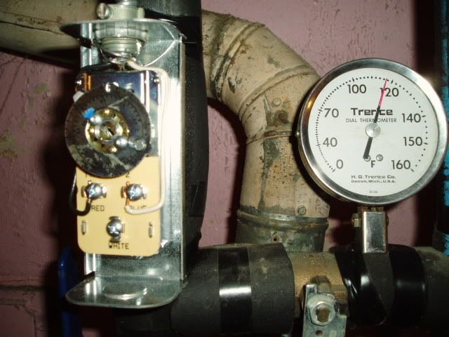
Can I use a different pump signal? I don't recall the pump running all the time when I only had the oil boiler for HW and heat.
