Dual Boiler Plumbing and Wiring.

 
User avatar
Sting
Member
Posts: 2983
Joined: Mon. Feb. 25, 2008 4:24 pm
Location: Lower Fox Valley = Wisconsin
Other Heating: OBSO Lennox Pulse "Air Scorcher" burning NG

Post by Sting » Fri. Aug. 27, 2010 2:26 pm

jaimz23 wrote:Thanks for the responses Sting, much obliged.

I do have a few new questions now. I am new to fan coil and ice cube relays so what/where do I wire the circulating pump and relays so that they see temperature? Do I splice them into somewhere? Or do the fan coil relays sense temperature somehow and activate the relay accordingly? In my head right now I am picturing from 120V to the fan coil relay to the circulating pump, but how does the fan coil relay see heat? Or am I way off?
AHHH -- your showing that you haven't read the wiring and controls comic book! :P ok I really cannot answer this one just yet as your still in discovery on how all the piping is coming together - but when that's all flushed out the control part won't be hard. Your beginning to discover that there is more than one correct way to do anything with this stuff.
jaimz23 wrote:This one I do understand. Flow check valve in the line between the oil boiler and the "T" allowing water to flow to the coal boiler and to the oil boiler but not from the oil boiler. Right?
Good job! I have never noted anyone doing it like this but I don't see why it will not work. Now that said, reread pumping away. You will note that each boiler - in that religion - would have its own pump on each supply to the main load manifold. And that's the way I might do it but - who cares? For my little system, I did something completely different because it was easier, and it works too.
jaimz23 wrote:The N.C. valve in the diagram's dump zone that I have will always be closed when power is applied thus only letting the pump pump water to the D.Z. if a over temp situation is reached. Then, if I buy a Circulating pump with a check valve in it that closes until power is applied to the pump, and the power goes out the N.C. valve will open and the check valve in the circulating pump will remain closed, thus allowing gravity to feed the hot water to the D.Z. Am I correct in assuming this?
Yes
jaimz23 wrote:Thanks again. PennCan Raceway tonight. Cheers!
A good time to be had - by all :D


jaimz23
Member
Posts: 130
Joined: Sun. Jan. 24, 2010 11:35 am
Hand Fed Coal Boiler: Harman Trident SF-260

Post by jaimz23 » Mon. Aug. 30, 2010 6:37 pm

Sting

You recently wrote this to me in a post about the optional loop circulator...

"Think of this guy as you would a traffic cop - he is there to make the return water want to go back to the coal boiler and not to the Oil boiler. You will - well I would wire it to run when ever the the coal boiler is above 145 degree sand whenever the load has any call for heat. ( just a couple of ice cube or fan coil relays will do) If the coal boiler falls below 140 wire it so the pump stops - because one of two things has happened - a] the system has overwhelmed the coal boiler output and this will protect the boiler from condensing temps plus allow it to recover and once it get back off its ass the pump will resume its duty to direct coal boiler energy into your system -- or b] the coal boiler has failed :oops: and we wire a back up into the system to launch the oil boiler to keep the house from going cold. note: the oil boiler can also fire on those really really cold nights to help out."

I responded confused and you knew I had not yet read the controls and wiring "comic book".....

Now I have read the section in the book on relays and now I do understand the connection of the relays, Thermostat is hooked up to energize the coil when it calls for heat, thus creating electromagnetic energy and making the contacts close (or open depending on its normal state) allowing 120V to flow to wherever it is needed....Now what I don't understand, lol. In your post at the top, you say to wire it so it runs when the coal boiler is above 145 degrees and whenever the load has any call for heat and wire it so it shuts off at 140 :?

What I am confused about is if I am to wire it to run at 145 and a call for heat and to stop at 140 degrees, this denotes connecting it to the aquastat and not the thermostat unless you have a Thermostat that goes to 145...and I am unsure of where exactly on the aquastat to connect it to to energize the relay coil and and get the contacts to close???? (Carol didn't cover this in her book only relay connection to thermostats and the loads) Also, if I needed to use 3 relays, one for each case (145, call for heat, and off at 140) where will all of these different 24V signals be coming from?

Last, for my N.C. Zone control valve in the dump zone (in my diagram) do they only run on 24V or are they available in 120V or do I need to plug 120V into a step down transformer to get 24V to power the N.C. zone control valve?

Thanks again, I am beginning to see the light at the end of the tunnel...Now to mow the lawn.

 
User avatar
Sting
Member
Posts: 2983
Joined: Mon. Feb. 25, 2008 4:24 pm
Location: Lower Fox Valley = Wisconsin
Other Heating: OBSO Lennox Pulse "Air Scorcher" burning NG

Post by Sting » Tue. Aug. 31, 2010 12:08 am

jaimz23 wrote:Sting
What I am confused about is if I am to wire it to run at 145 and a call for heat and to stop at 140 degrees, this denotes connecting it to the aquastat and not the thermostat unless you have a Thermostat that goes to 145...and I am unsure of where exactly on the aquastat to connect it to to energize the relay coil and and get the contacts to close???? (Carol didn't cover this in her book only relay connection to thermostats and the loads) Also, if I needed to use 3 relays, one for each case (145, call for heat, and off at 140) where will all of these different 24V signals be coming from?
Image
OK - you see the benefit of reading a little first ; and now disguised as a toilet seat - you will get more tail than I --

or

what your missing here is your signal generator - commonly referred to as an Aquastat. Something like this:
Image
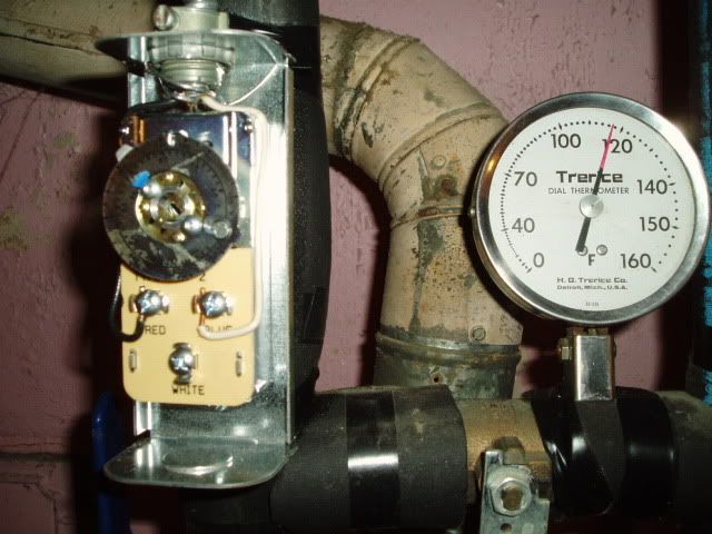
I have the cover off this one so you can see the wiring - its wired to OPEN the 120 volt signal to the pump that charges my domestic hot water tank to 120 degrees - so.... when the tank gets to 120 this switch (aquastat) opens and stops the pump. Now these have a differential - the amount of temperature that the switch rests prior to reaction to temperature rise and fall. Some are adjustable. This could just as easily be a 24 volt signal controlling a zone valve and sending a 24 volt signal to another relay that opens and closes a 120 volt signal to a pump and so on and so on.

These will control ONE 24 volt control signal or circuit or ONE 120 volt circuit (or one hi voltage signal if your using 120 volt ice cube relays) more on this below

In your case above - you will find a place to strap on one of these like I did here, only set at about 140-145 - or your will have or create a temperature well in a fitting close to the boiler - to place the probe of one of these and wire the circulator pump ( or possibly you will use the C1 and C2 terminals of the triple aqustat on your coal boiler to do the same - but I don't like that - more on this later. There are many ways to do this just like Windows. Read a little more about the boiler controls.

The goal is - you don't want to send cold water into your hot boiler to shock it and you don't want to run your boiler below 140 or you will get corrosive condensation. And you don't want to pump the boiler when there is no call for heat to the load, because that wastes pump and boiler energy.
Do a search for boiler protection.
This is how its done the simple way. ;) Lots of folks make expensive logic controls that cost zillions, and are impossible to repair on a Sunday evening while the Packers game is on. I have sort of a "distaste" for that.
Now these signal generators (aquastat) can control one device pump valve etc. They are a single pole single throw - normally open or normally closed switch. When you daisy chain signals - lets say this must happen before this can - you use relays to isolate signals from one another so that doesn't cause this to happen before that. and so on. I have to make you read the books and search a little more or Ill be writing the book here.
jaimz23 wrote:Last, for my N.C. Zone control valve in the dump zone (in my diagram) do they only run on 24V or are they available in 120V or do I need to plug 120V into a step down transformer to get 24V to power the N.C. zone control valve
Ice cube relays can be purchased that do this any way you want.

http://www.grainger.com/Grainger/wwg/search.shtml ... sst=subset

or

http://www.grainger.com/Grainger/WHITERODGERS-Fan ... Pid=search

It depends

Let me get back to you :D

or better -- Lets get YANCHE to take a swing here.

 
jaimz23
Member
Posts: 130
Joined: Sun. Jan. 24, 2010 11:35 am
Hand Fed Coal Boiler: Harman Trident SF-260

Post by jaimz23 » Tue. Aug. 31, 2010 4:01 pm

Sting, you are the man. Thanks for the guidance and pointing me in the right direction.

I do have one last question for you on a bit of a different subject.
If I were to have my boilers plumbed in the manner I have in my diagram, which circulators should have check valves?

I know I need a circulator with a check valve to be in the dump zone in case the power goes out allowing gravity to force hot water through only the zone valve, but at the bottom of the return zone, in the optional loop circulator, if I had a pump with a check valve in it there, gravity would only be able to force water to the back of the pump, thus stopping the dump zone circulation.

Also, would I want a check valve in the primary zone circulator? Because if there is one there, the hot water will not travel up to the radiators on my first floor by gravity either, because of the c.v. in the pump, thus eliminating any heat at all getting to the first floor of my house.

Or, do I just run a separate return line from the dump zone to the coal boilers return line after the optional circulation pump?
Would that help?

Thanks

 
User avatar
Sting
Member
Posts: 2983
Joined: Mon. Feb. 25, 2008 4:24 pm
Location: Lower Fox Valley = Wisconsin
Other Heating: OBSO Lennox Pulse "Air Scorcher" burning NG

Post by Sting » Tue. Aug. 31, 2010 4:34 pm

jaimz23 wrote:Sting, you are the man. Thanks for the guidance and pointing me in the right direction.

I do have one last question for you on a bit of a different subject.
If I were to have my boilers plumbed in the manner I have in my diagram, which circulators should have check valves?

I know I need a circulator with a check valve to be in the dump zone in case the power goes out allowing gravity to force hot water through only the zone valve, but at the bottom of the return zone, in the optional loop circulator, if I had a pump with a check valve in it there, gravity would only be able to force water to the back of the pump, thus stopping the dump zone circulation.

Also, would I want a check valve in the primary zone circulator? Because if there is one there, the hot water will not travel up to the radiators on my first floor by gravity either, because of the c.v. in the pump, thus eliminating any heat at all getting to the first floor of my house.
The checks in the pump are closed, not just opposing flow, unless the pressure opens it. so they stop flow in both directions unless it's strong enough to lift the check. You might also consider a thermal flow prevention loop as pictured here on each return.
Image
jaimz23 wrote:Or, do I just run a separate return line from the dump zone to the coal boilers return line after the optional circulation pump?
Would that help?
Now your "Thinking like the Water"Image

 
jaimz23
Member
Posts: 130
Joined: Sun. Jan. 24, 2010 11:35 am
Hand Fed Coal Boiler: Harman Trident SF-260

Post by jaimz23 » Mon. Sep. 13, 2010 7:11 pm

Ah yes, I may be just over thinking this from staring at my Microsoft paint diagram that I have created that should work for my SF-260 add on to my existing boiler. But here is my question...When my primary aquastat turns on to supply the radiators with hot water, it will pull water from the coal boiler and partially from the oil boiler also, but mostly from the coal boiler because the water is hot and wanting to rise already. But, my optional loop circulator in between the boilers will stop any water from returning to the coal boiler because of its check valve right? Or will water already be moving because of the settings that I will have the optional circulator's aquastat on?

Also, if the optional circulator is on and trying to move the water and the Main circulator is not on because no heat is needed, it isn't going to move water because of the check valve in the main circulator pump? Should I add another small copper pipe from the boiler feed to the return to allow the optional circulator pump to move water? (which I have put in my drawing with a bright blue - - - - - line.

I know you showed a picture with a thermal flow protection, but my set up is not like that at all and from what I can tell it is Primary - Secondary flow which I am not doing.

Thanks again

Attachments

Boiler add on with wiring finished 2.jpg
.JPG | 115.8KB | Boiler add on with wiring finished 2.jpg

 
User avatar
JB Sparks
Member
Posts: 842
Joined: Sun. Oct. 19, 2008 8:09 pm
Location: north central Mass.

Post by JB Sparks » Mon. Sep. 13, 2010 7:55 pm

Yup, I believe your thinking too much. First, do not install that small pipe from your dump zone back to the return line. It is fine the way you had it. Your S350 relay will activate the dump zone circ. if the boiler water gets too hot. Second you don't need a check valve in the return line or what you are calling the optional loop circ. line. You should leave that circ. running 24/7 and it will keep the water in both boilers at the same temp.all the time, that is desirable. And with no check valve your dump zone will work in a no power condition. This also keeps the oil boiler water from dropping below condensation temps. When your house calls for heat your main circ. comes on and takes water from both boilers which is ok, they are at the same temp. This to me is the nice thing about having the boilers hooked up in parallel. I use a grundfor three speed pump for the circ. between the boilers and keep it on the lowest speed. Works great. The only difference between your set up and mine is you are making a separate dump zone, I use a relay and bring on all zone at once when the S350 relay activates. Everything else will be the same.

Hope this helps a little.
JB


jaimz23
Member
Posts: 130
Joined: Sun. Jan. 24, 2010 11:35 am
Hand Fed Coal Boiler: Harman Trident SF-260

Post by jaimz23 » Mon. Sep. 13, 2010 8:22 pm

JB Sparks wrote:Yup, I believe your thinking too much. First, do not install that small pipe from your dump zone back to the return line. It is fine the way you had it. Your S350 relay will activate the dump zone circ. if the boiler water gets too hot. Second you don't need a check valve in the return line or what you are calling the optional loop circ. line. You should leave that circ. running 24/7 and it will keep the water in both boilers at the same temp.all the time, that is desirable. And with no check valve your dump zone will work in a no power condition. This also keeps the oil boiler water from dropping below condensation temps. When your house calls for heat your main circ. comes on and takes water from both boilers which is ok, they are at the same temp. This to me is the nice thing about having the boilers hooked up in parallel. I use a grundfor three speed pump for the circ. between the boilers and keep it on the lowest speed. Works great. The only difference between your set up and mine is you are making a separate dump zone, I use a relay and bring on all zone at once when the S350 relay activates. Everything else will be the same.

Hope this helps a little.
JB
You might be viewing my picture wrong (I do see how this could happen it is kinda confusing.) The small pipe was not coming from my dump zone back to the return line. It is coming from the main feed line directly off of the coal boiler but after the dump zone and back to the return line. The only reason I did this, is because I am trouble understanding how the loop circulator will be able to pull water from the oil boiler to the coal boiler and keep both boilers at the same temp. if it cannot circulate somewhere. How is this set up going to keep the water in the oil boiler at the same temp as the coal boiler?? How is warm water getting into the oil boiler? How is this loop working properly even if it is on all the time how is it circulating in a loop??

Confused once again.

 
jaimz23
Member
Posts: 130
Joined: Sun. Jan. 24, 2010 11:35 am
Hand Fed Coal Boiler: Harman Trident SF-260

Post by jaimz23 » Mon. Sep. 13, 2010 8:41 pm

Wait...maybe we are getting our signals crossed. I was talking about the light blue line that I drew in with Microsoft paint on the left side of the return line, the 90 degree angle line.

I was wondering if I needed this line for circulation purposes or will it somehow be okay without this line?

Second, are you referring to the small dark blue return line coming from the bottom of my dump zone and going back to the coal boiler after the loop circulator?

Is that the one that you are saying I don't need??

Even if this loop circulator pump were running all the time, where will the water go from it without the main circulator running? Where is the loop to keep the water moving if the main circulator is not on because the circulators have check valves and won't open unless called upon to do so.

And again how is this set up able to keep both boilers at the same temperature. When all it is doing is pulling water from the return line into the coal boiler?

Or am I not understanding that this circulator can pull cold water from the oil boiler and get it back from the supply side into the oil boiler thus keeping the water in there hot until the main circ. calls for hot water and is set at a higher speed and pulls the water away and into my main zone?

Whew...
Last edited by jaimz23 on Mon. Sep. 13, 2010 8:52 pm, edited 1 time in total.

 
User avatar
JB Sparks
Member
Posts: 842
Joined: Sun. Oct. 19, 2008 8:09 pm
Location: north central Mass.

Post by JB Sparks » Mon. Sep. 13, 2010 8:42 pm

Ok, I just went back and looked at your first drawing, you just changed where the dump zone return line connects into the main return line or am I still missing something. With your loop pump running all the time it shouldn't make any difference where it connects as long as you don't have a check valve in the main return line between the two boilers. If you take a look at your drawing you can see that with the loop pump running and the main circ. off or not calling the boiler water will continue to circulate between the two boilers which will keep them at the same temp.

 
User avatar
JB Sparks
Member
Posts: 842
Joined: Sun. Oct. 19, 2008 8:09 pm
Location: north central Mass.

Post by JB Sparks » Mon. Sep. 13, 2010 8:44 pm

Ok I see the line you are talking about. No you don't need that line it will not accomplish anything.

 
jaimz23
Member
Posts: 130
Joined: Sun. Jan. 24, 2010 11:35 am
Hand Fed Coal Boiler: Harman Trident SF-260

Post by jaimz23 » Mon. Sep. 13, 2010 9:03 pm

No, you are correct, that is what I changed. I did this because I didn't think about running the loop circulator all the time and was unsure how the water from the dump zone would get back to the coal boiler. I do understand what you are saying, but another reason for the dump zone return line going past the loop circulator and closer to the coal boiler is also because if my power goes out, how is the return water, that will be gravity fed from my Check valve popping open get to the coal boiler and allow circulation if the power is off and the loop circulator is not moving any water and my dump zone return is plumbed behind it??

Won't that eliminate the ability to do a gravity fed zone if my power should fail if my D.Z. is plumbed behind the loop circulator which requires power?

I know I am being somewhat redundant, but I just want to make sure I am being clear.

 
User avatar
JB Sparks
Member
Posts: 842
Joined: Sun. Oct. 19, 2008 8:09 pm
Location: north central Mass.

Post by JB Sparks » Mon. Sep. 13, 2010 9:15 pm

If there is no built-in check valve in the circ. or in the return line itself, water will gravity feed through the pump wether it's running or not, however I think your right in that it will flow less restricked the way you piped it in the second drawing.

 
jaimz23
Member
Posts: 130
Joined: Sun. Jan. 24, 2010 11:35 am
Hand Fed Coal Boiler: Harman Trident SF-260

Post by jaimz23 » Mon. Sep. 13, 2010 9:37 pm

JB Sparks wrote:If there is no built-in check valve in the circ. or in the return line itself, water will gravity feed through the pump wether it's running or not, however I think your right in that it will flow less restricked the way you piped it in the second drawing.
Thanks. I was hoping that I had it the correct way.

On the other note, for some reason, I didn't realize the loop circulator could pull cold water out of the oil boiler and into the coal boiler creating a loop all the time (if it's wired to 120V to run constantly.) I just had a mental block not allowing me to figure that out, but I thank you for the assistance and it is nice to know someone who has a coal and oil boiler set up like mine that is already plumbed and wired allowing me to see if my monster of a diagram will work.

Thanks again, I think I got it all figured out now.

1. I won't run a aquastat to the loop circulator, I'll just wire it to run constantly at low speed.
2. My Dump Zone setup is looking correct with the 2 different ways to run the water. Circulator powered by the 350 for over temp and Normally open zone valve for power fail and all plumbed after the loop circulator on the return side for gravity purposes.
3. Main circulator will kick on when the main zone needs heat and pull water from both boilers that are now at the same temp.

:D Thanks Again

 
User avatar
Sting
Member
Posts: 2983
Joined: Mon. Feb. 25, 2008 4:24 pm
Location: Lower Fox Valley = Wisconsin
Other Heating: OBSO Lennox Pulse "Air Scorcher" burning NG

Post by Sting » Mon. Sep. 13, 2010 9:41 pm

jaimz23 wrote:Ah yes, I may be just over thinking this from staring at my Microsoft paint diagram that I have created that should work for my SF-260 add on to my existing boiler. But here is my question...When my primary aquastat turns on to supply the radiators with hot water, it will pull water from the coal boiler and partially from the oil boiler also, but mostly from the coal boiler because the water is hot and wanting to rise already. But, my optional loop circulator in between the boilers will stop any water from returning to the coal boiler because of its check valve right? Or will water already be moving because of the settings that I will have the optional circulator's aquastat on?
over-thinking ??? yes and no -- Think like the water. When the primary aquastat - as you say - turns on and energy begins to flow out to zones and back -- and here is the key - when it (the water) comes back.... That "traffic cop" circulator (remember me telling you to think about it like that? ) will turn the "water" (like a cowboy turns the stampede of cattle) back into the coal boiler to be recharged with heat energy and pumped back out to your load. if the coal boiler is cold - you need a boiler protection aquastat wired to open on temperature drop of say 140 so the traffic cop pump stops - either because the coal boiler is over whelmed or the coal boiler has failed. Then the Oil boiler should be wired on a separate house stat ( set below comfort temperature) to bring it on line when/if the house temp drops - so it can pick up the load with the water that is short circuiting thru it.
jaimz23 wrote:Also, if the optional circulator is on and trying to move the water and the Main circulator is not on because no heat is needed, it isn't going to move water because of the check valve in the main circulator pump? Should I add another small copper pipe from the boiler feed to the return to allow the optional circulator pump to move water? (which I have put in my drawing with a bright blue - - - - - line.
both circulators will run in concert when the coal boiler is hot ;) see above. I have no idea what little pipe you may be referring to here. You may be over fixating on this dump zone and not on the target -- heating your house.
jaimz23 wrote:I know you showed a picture with a thermal flow protection, but my set up is not like that at all and from what I can tell it is Primary - Secondary flow which I am not doing.

Thanks again
now your over thinking again -- the picture was posted only to show you what a loop looks like to dampen thermal flow.


Post Reply

Return to “Stoker Coal Boilers Using Anthracite (Hydronic & Steam)”